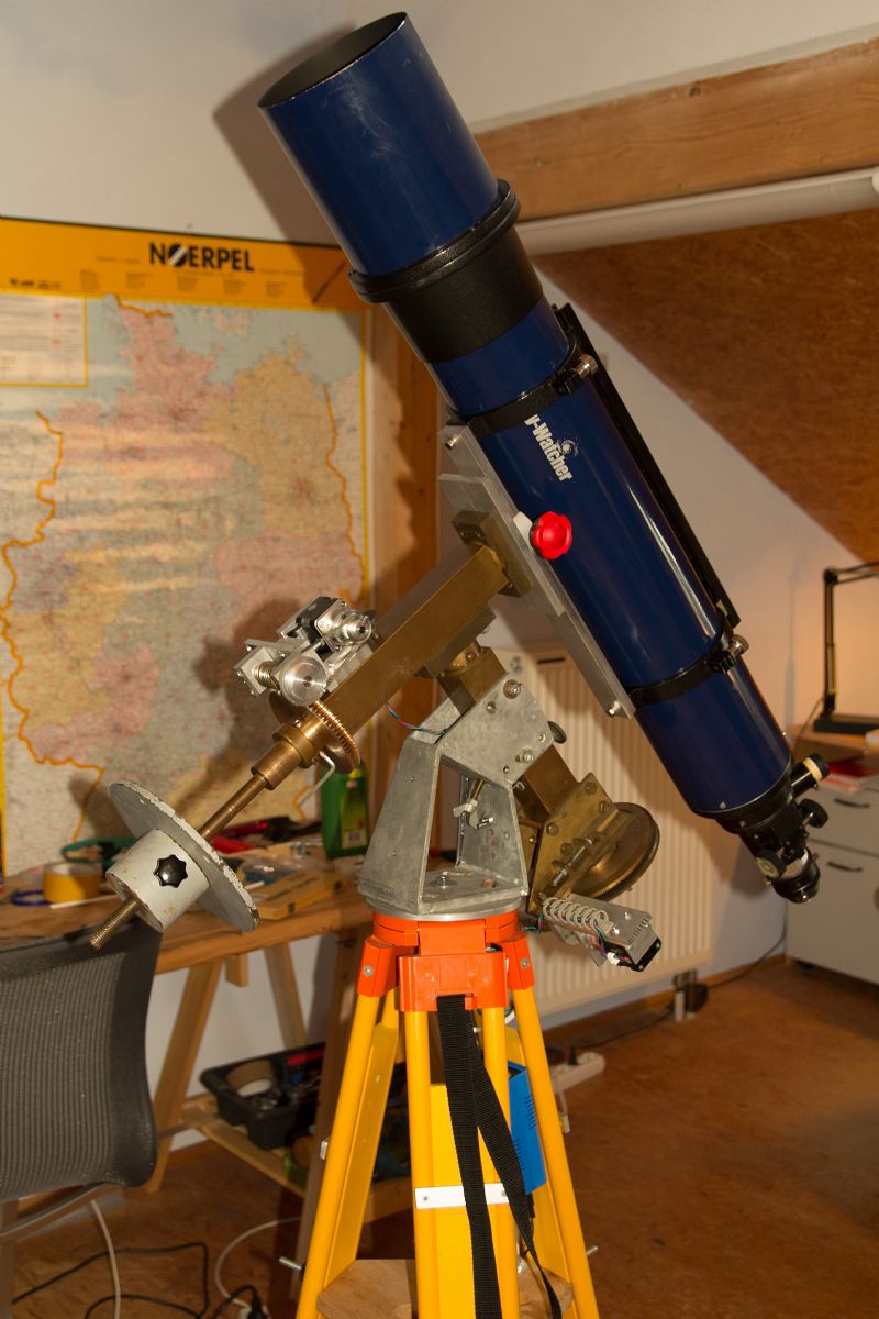
Hallo Gerrit,
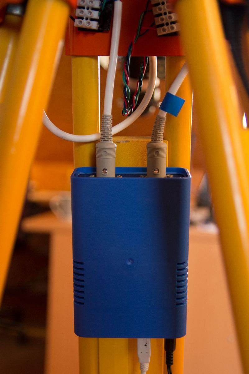
hier meine aktuelle Config.h, mit der sky planetarium prinzipiell funktioniert. Bei "Guide & Focus" geht der "VFast" Betrieb beim DEC Stepper nicht, der Stepper beschleunigt 2 sec, jault auf, und die Bewegung stoppt. Im "Fast" Modus geht es, von der Geschwindigkeit reicht es auch, für 90° benötigt der DEC Stepper ca. 27 sec. Was mir nicht gefällt, sind die ratternden Schrittmotorgeräusche, bei "Mid" Betrieb, offenbar arbeitet OnStep hier mit 1 oder 2 Microsteps.
Bei RA läuft das wesentlich feiner, obwohl die MS Einstellung für RA und DEC gleich ist.
Aber das sind keine schwerwiegenden Probleme, vielleicht kann ich hier mit ein bisschen Finetuning etwas verbessern.
Die Berechnungen für die Anpassung auf meine Übersetzungsverhältnisse habe ich in den Kommentaren für StepsPerDegreeHA und DE vermerkt.
Vielleicht gibt es ja noch Tipps zum Verbessern.
Viele Grüße
Carsten
// -----------------------------------------------------------------------------------
// Configuration CW
/*
* The Arduino Mega2560 and Teensy3.1 use USB for power and communication with the host computer
*
* the RA stepper driver plugs into Pins Gnd,13,12, and 11 (Gnd,Step,N/C,Dir... Teensy3.1 uses Gnd,12,11,10.)
* the Dec driver plugs into pins 7, 6, 5, and 4 (OnStep pulls 7 LOW to simulate Gnd, and the wiring is identical.)
* RA : Gnd,13,12,11 = Gnd,Step,N/C,Direction (Teensy3.1 Gnd,12,N/C,10)
* Dec: 7, 6, 5, 4 = Gnd,Step,N/C,Direction (Teensy3.1 Gnd, 6,N/C, 4)
*
* The easiest option is to use two SparkFun Big Easy Drivers (BED) to control the
* bipolar stepper motors; with proper heat-sinks they can handle up to 2A per phase at 35V.
* Each BED can be setup by soldering a 4-position male .1" header into the input side.
* I modified the header by removing the 2nd to last pin, and bending the last pin so
* the header fits into the Gnd,Step,Dir holes of the BED. A four wire ribbon cable from
* Sparkfun, etc. can then be used to plug them into the Arduino. The outputs go to the
* two coils of each stepper motor. If you don't know which wires are which, the 'net is
* full of advise on determining what you have, google it and get out your multimeter.
* Refer to my site (Equipment->OnStep) and/or read up on the 'net to get an idea of how
* to set the potientiometer on the BEDs to match your stepper motors; too much current
* will BURN OUT YOUR STEPPER MOTORS.
*
* Optionally, the status LED plugs into pins 9,8. I use an 2.2k resistor in series with the LED.
* LED: 9,8 = Gnd,+5V
*
* Optionally, a bluetooth adapter (HC05 or RN42 for example) plugs into pins Tx1/Rx1 and pins +5V/Gnd.
* I use two 2-wire cables for 0.1" headers. Remember Rx goes to Tx and Tx goes to Rx. And be
* sure to get a BT module designed for 5 volt operation and signaling otherwise you'll have to design
* and implement the level conversion hardware yourself.
* BT: Tx,Rx/+5V,Gnd = Rx1,Tx1/+5V,Gnd
*
*/
// -------------------------------------------------------------------------------------------------------------------------
// ADJUST THE FOLLOWING TO CONFIGURE YOUR CONTROLLER FEATURES --------------------------------------------------------------
// turns debugging on, used during testing, default=OFF
#define DEBUG_OFF
// for getting control of the 'scope when things go horribly wrong, default=OFF
#define RESCUE_MODE_OFF
// Mount type, default is _GEM (German Equatorial) other options are _FORK, _FORK_ALT. _FORK switches off Meridian Flips after (1, 2 or 3 star) alignment is done. _FORK_ALT disables Meridian Flips (1 star align.)
// _ALTAZM will be for Alt/Azm mounted 'scopes, but isn't implemented yet.
#define MOUNT_TYPE_GEM
// Experimental ST4 interface on pins 47, 49, 51, 53. Pin 47 is RA- (West), Pin 49 is Dec- (South), Pin 51 is Dec+ (North), Pin 53 is RA+ (East.) Teensy3.1 pins 24, 25, 26, 27.
// ST4_ON enables the interface. ST4_PULLUP enables the interface and the any internal pullup resistors.
// It is up to you to create an interface that meets the electrical specifications of any connected device, use at your own risk.
#define ST4_OFF
// PPS sense rising edge on pin 21 for optional precision clock source (GPS, for example), default=OFF (Teensy3.1 Pin 23)
#define PPS_SENSE_OFF
// PEC sense, rising edge (default with PEC_SENSE_STATE HIGH, use LOW for falling edge) on pin 2 (ex. PEC_SENSE_ON) or threshold value on Analog 1; for optional PEC index, default=OFF
// analog values range from 0 to 1023 which indicate voltages from 0-5VDC on the A1 pin, for example "PEC_SENSE 600" would detect an index when the voltage exceeds 2.92V
// with either index detection method, once triggered 60s must expire before another detection can happen. This gives time for the index magnet to pass by the detector before another cycle begins.
// Note: Analog PEC index sense is not supported on the Teensy3.1
#define PEC_SENSE_ON
#define PEC_SENSE_STATE HIGH
// switch close (to ground) on pin 3 for optional limit sense (stops gotos and/or tracking), default=OFF
#define LIMIT_SENSE_OFF
// light status LED by sink to ground (pin 9) and source +5V (pin 8), default=ON
// _ON and OnStep keeps this illuminated to indicate that the controller is active. When sidereal tracking this LED will rapidly flash with RA step pulses
#define STATUS_LED_PINS_ON
// lights 2nd status LED by sink to ground (pin 10), default=OFF, must be off for Teensy3.1 (pin 7)
// _ON sets this to blink at 1 sec intervals when PPS is synced
// n sets this to dimly light a polar finder reticle, for example I use STATUS_LED2_PINS 250
#define STATUS_LED2_PINS_OFF
// optional +5V on pins 5 and 12 to Pololu or other stepper drivers without on-board 5V voltage regulators, default=OFF (Teensy3.1 Pins 5,11)
#define POWER_SUPPLY_PINS_OFF
// optional stepper driver Enable support is always on, just wire Enable to Pins 25 (HA) and 30 (Dec) and OnStep will pull these HIGH (Teensy3.1 Pins 16,21)
// by default to disable stepper drivers on startup and when Parked. An Align or UnPark will enable the drivers. Adjust below if you need these pulled LOW to disable the drivers.
#define HA_DISABLED_HIGH
#define DE_DISABLED_HIGH
// enables Horizon coordinate goto functions, default=ON
#define ALT_AZM_GOTO_ON
// enables code to clean-up PEC readings after record (use PECprep or a spreadsheet to fix readings otherwise)
// this cleans up any tracking rate variations that would be introduced by recording more guiding corrections to either the east or west, default=ON
#define PEC_CLEANUP_ON
// optionally adjust tracking rate to compensate for atmospheric refraction, default=OFF (limited testing done)
// can be turned on/off with the :Te# and :Td# commands regardless of this setting
#define TRACK_REFRACTION_RATE_DEFAULT_OFF
// use seperate pulse-guide rate so centering and guiding don't disturb eachother, default=OFF
#define SEPERATE_PULSE_GUIDE_RATE_ON
// these turn on and off checksum error correction on the serial ports, default=OFF
#define CHKSUM0_OFF // default _OFF: required for OnStep ASCOM driver
#define CHKSUM1_OFF // default _OFF: required for OnStep Controller2 Android App (and others)
// ADJUST THE FOLLOWING TO MATCH YOUR MOUNT --------------------------------------------------------------------------------
#define RememberMaxRate_OFF // set to ON and OnStep will remember rates set in the ASCOM driver or Android App (when supported), default=OFF
#define MaxRate 96 // this is the minimum number of micro-seconds between micro-steps
// minimum* (fastest goto) is around 16 (Teensy3.1) or 32 (Mega2560), default is 96, higher is ok
// too low and OnStep communicates slowly and/or freezes as the motor timers use up all the MCU time
// * = minimum can be lower, when both HA & DE_MODE_GOTO are used by HA/DE_STEP_GOTO times.
#define StepsForRateChange 200000.0 // number of steps during acceleration and de-acceleration: higher values=longer acceleration/de-acceleration
// for the most part this doesn't need to be changed, but adjust when needed
#define BacklashTakeupRate 25 // backlash takeup rate (in multipules of the sidereal rate): too fast and your motors will stall,
// too slow and the mount will be sluggish while it moves through the backlash
// for the most part this doesn't need to be changed, but adjust when needed
// this should be 60 or lower
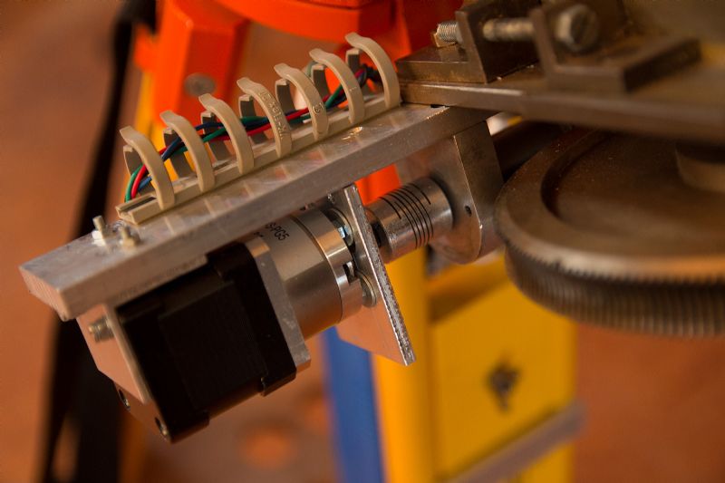
// for my mounts both RA and Dec axis have the same gear train
#define StepsPerDegreeHA 13265L // calculated as : stepper_steps * micro_steps * gear_reduction1 * (gear_reduction2/360)
// CW Montierung : 200 * 32 * 5.181818 * 144/360 = 13265
// Takahashi EM10b : 48 * 16 * 50 * (45/36) * 144/360 = 19200
// Losmandy G11 : 400 * 32 * 1 * 360/360 = 12800
#define StepsPerDegreeDec 13818L // calculated as : stepper_steps * micro_steps * gear_reduction1 * (gear_reduction2/360)
// CW Montierung : 200 * 32 * 5.181818 * 2 (Zahnriemenantrieb 60Z/30Z) * 75/360 = 13818
// Takahashi EM10b : 48 * 16 * 50 * (45/36) * 144/360 = 19200
// Losmandy G11 : 400 * 32 * 1 * 360/360 = 12800
// the EM10b has two spur gears that drive the RA/Dec worms, they are 60 tooth and 48 tooth gears
// for an 1.25x reduction in addition to the 50:1 gear heads on the steppers for a 62.5:1 final ratio
// before the worm/wheels 144:1
#define StepsPerSecond 55.3 // the steps per second sidereal rate = (19200/3600)*15 = 80 - OnStep can handle between 12 and 100 steps/second
// StepsPerSecond doesn't need to be an integer
// StepsPerWormRotation (for PEC) needs to be evenly divisible by StepsPerSecond
#define StepsPerWormRotation 33163L // PEC, number of steps for a complete worm rotation (in RA), (StepsPerDegreeHA*360)/gear_reduction2
// the EM10b has a worm-wheel with 144 teeth (19200*360)/144 = 48000
// According to this the EM10b needs 600 (seconds) of PEC buffer. Since the transfer gears have a rather large effect on the periodic error
// I have two options 1. use 4x the 48000 = 192000 (2400 seconds.) This is 4 complete rotations of the worm and 5 complete rotations of the transfer gear.
// I expect the results would be very good, but since PECPrep is limited to 1000S I don't bother.
// 2. use 480 (seconds) of PEC buffer. This is easier to program and keeps the PE at low levels
// so pretending we have 180 teeth (19200*360)/180 = 38400
#define PECBufferSize 2400 // PEC, buffer size, max should be no more than 3384, your required buffer size >= StepsPerWormRotation/StepsPerSecond
// for the most part this doesn't need to be changed, but adjust when needed. 824 seconds is the default
#define REVERSE_HA_OFF // reverse the direction of movement for the HA/RA axis, adjust as needed or reverse your wiring so things move in the right direction
#define REVERSE_DEC_OFF // reverse the direction of movement for the Dec axis (both reversed for my EM10b, both normal for G11)
#define minutesPastMeridianE 60 // for goto's, how far past the meridian to allow before we do a flip (if on the East side of the pier) - one hour of RA is the default = 60
#define minutesPastMeridianW 60 // as above, if on the West side of the pier. If left alone, the mount will stop tracking when it hits the this limit
#define underPoleLimit 9 // maximum allowed hour angle (+/-) under the celestial pole. OnStep will flip the mount and move the Dec. past 90 degrees (+/-) once past this limit
// to arrive at the location. If left alone, the mount will stop tracking when it hits this limit. Valid range is 7 to 11 hours
#define minDec -91 // minimum allowed declination, default = -91 (off)
#define maxDec +91 // maximum allowed declination, default = 91 (off)
// For example, a value of +80 would stop gotos/tracking near the north celestial pole.
// For a Northern Hemisphere user, this would stop tracking when the mount is in the polar home position but
// that can be easily worked around by doing an alignment once and saving a park position
// Micro-step driver mode control
// M0, M1, and M2 are on Pins 22,23, and 24 for RA (Teensy3.1 Pins 13,14,15.) M0, M1, M2 are on Pins 27,28,29 for Dec (Teensy3.1 Pins 18,19,20.)
// DRV8825: 5=32x, 4=16x, 3=8x, 2=4x, 1=2x, 0=1x
#define HA_MODE_5 // programs the HA uStep mode M0/M1/M2, optional and default _OFF. Other values 0 to 7 (0xb000 to 111): for example "#define HA_MODE 4"
#define HA_MODE_GOTO_4 // programs the HA uStep mode M0/M1/M2, used during gotos, optional and default _OFF. Other values 0 to 7 (0xb000 to 111): for example "#define HA_MODE_GOTO 4"
#define HA_STEP_GOTO 2 // 1=goto mode is same as normal mode: for example if normal tracking mode is 32x and goto is 8x this would be 4
#define DE_MODE_5 // programs the Dec uStep mode M0/M1/M2, optional and default _OFF. Other values 0 to 7 (0xb000 to 111)
#define DE_MODE_GOTO_4 // programs the Dec uStep mode M0/M1/M2, used during gotos, optional and default _OFF. Other values 0 to 7 (0xb000 to 111)
#define DE_STEP_GOTO 2 // 1=goto mode is same as normal mode: for example if normal tracking mode is 32x and goto is 8x this would be 4
// THAT'S IT FOR USER CONFIGURATION!
// -------------------------------------------------------------------------------------------------------------------------